
Optimizing Passive Cooling
A Comparative Study on SFP Heat Dissipation in Fanless Devices
Introduction
In the world of high-speed networking, heat is the ultimate performance killer. When you’re designing a fanless, passive networking device, SFP (Small Form-factor Pluggable) modules become tiny furnaces that can throttle your data or degrade your optics if not managed correctly.
We recently ran a series of thermal stress tests to find out how a simplified adhesive-based design compares to a screw-mounted design. Here is what we found.
The Challenge: Bridging the 12mm Gap
Our device features a 12mm vertical gap between the SFP cage and the aluminum enclosure. To bridge this, we utilized WE-TGFG Thermal Graphite Foam Gaskets – high-performance interface materials with a massive thermal conductivity of 400 W/(m⋅K).
We tested three distinct scenarios to find the best balance between cooling efficiency and manufacturing and assembly cost.
Sampling Methodology
Testing focused on two specific ports to capture the device’s thermal profile:
- Port 0: One of the ports near the edge of the PCB.
- Port 2: One of the inner ports. Internal ports (P1 and P2) consistently measure higher temperatures than edge ports (P0 and P3) due to thermal soak from surrounding components.
The Three Testing Scenarios
- Scenario 1 – The “Dual-TIM Sandwich” (10mm Block): A simplified aluminum block with thermal gaskets on both sides. This relies on the device’s internal ESD springs to press the assembly against the enclosure.
- Scenario 2 – The “Single-TIM Lean” (12mm Block): A taller block using only one gasket. This reduces the bill of materials but relies on “dry” metal-to-metal contact with the enclosure and requires non-standard extrusion sizes.
- The “Old School” Screw-Down (12mm Block): A traditional mechanical approach where the block is physically screwed to the PCB to force compression.
Thermal Performance Summary
After reaching a 3-hour steady state, the data revealed that the most complex solution was actually the least effective.
Thermal Performance Summary
| Metric | Scenario 1 (Dual-TIM) | Scenario 2 (Single-TIM) | Scenario 3 (Screwed) |
| Port 0 (P0) Stable Avg | 42.44°C | 43.57°C | 45.37°C |
| Port 2 (P2) Stable Avg | 45.45°C | 46.58°C | 47.35°C |
| Max Port 2 (P2) Temp | 46.00°C | 47.00°C | 47.75°C |
| Avg Room Temp | ≈25.47°C | ≈25.85°C | ≈25.44°C |
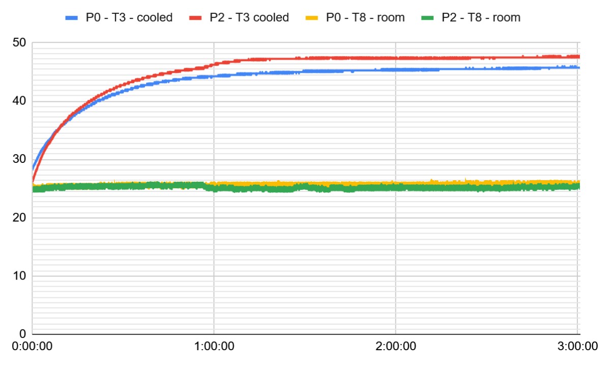
Figure 1 – Temperature graph for Scenario 1
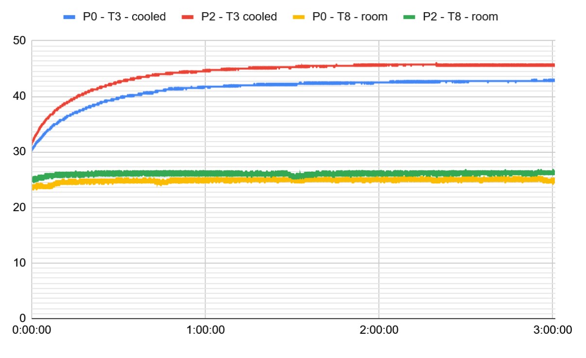
Figure 2 – Temperature graph for Scenario 2z
Figure 3 – Temperature graph for Scenario 3
While the thermal lead of Scenario 1 is approximately 1.1–2.0°C, the real victory lies in the performance-to-cost ratio. Scenario 1 achieved the best results using the most economical assembly method.
Technical Analysis: The Mechanical Risk
1. Thermal Contact Resistance vs. Mechanical Pressure
The “Old School” screw-down method (Scenario 3) paradoxically performed worst. This highlights a fundamental mechanical risk: high-torque mounting often introduces PCB bowing and component deformation. These unequal forces create larger pockets of trapped air at the block-to-enclosure interface.
In contrast, the foam core of the WE-TGFG gasket “wets” the surface, flowing into microscopic peaks and valleys of the aluminum. This minimizes Thermal Contact Resistance (Rc) far more effectively than raw mechanical force on a dry interface.
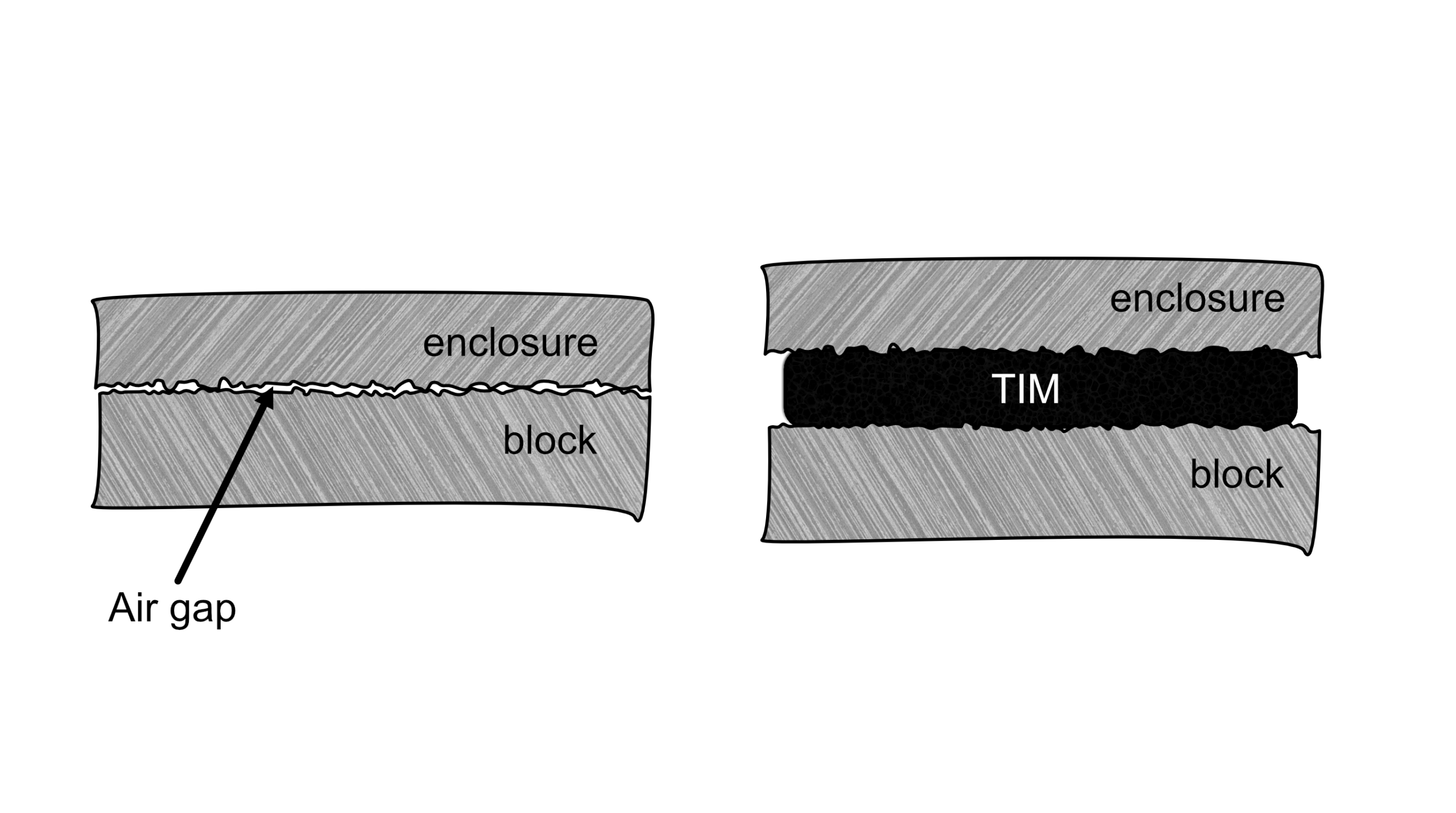
Figure 4 – Thermal Interface Material Wetting Surfaces
2. The ESD Spring Advantage
The SFP cage’s internal ESD springs act as a natural clamping mechanism. In Scenario 1, these springs press the 10mm block and dual-gasket stack upward into the gap. This ensures the material stays within its 1.35–1.05mm recommended working height, creating a self-tensioning thermal bridge without a need for tensioning.
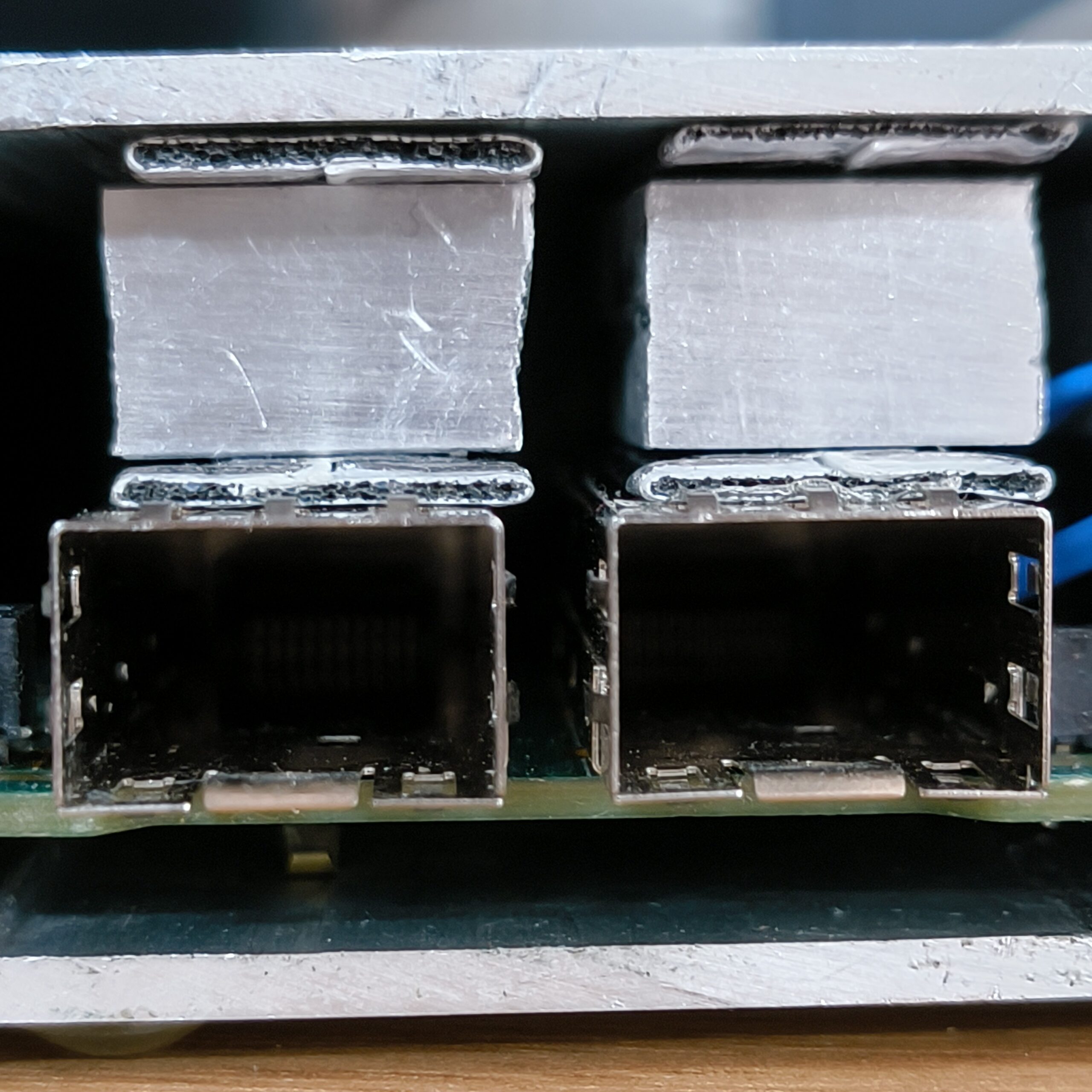
Figure 5 – Stack with ESD spring
3. Manufacturing and Sourcing
- Scenario 1 uses a standard 10mm×15mm aluminum extrusion, which is easy to source and requires no custom machining, just cutting to length.
- Scenario 2 & 3 Require non-standard or larger footprints (12mm), leading to increased material waste, higher unit costs, and longer procurement lead times.
-
-
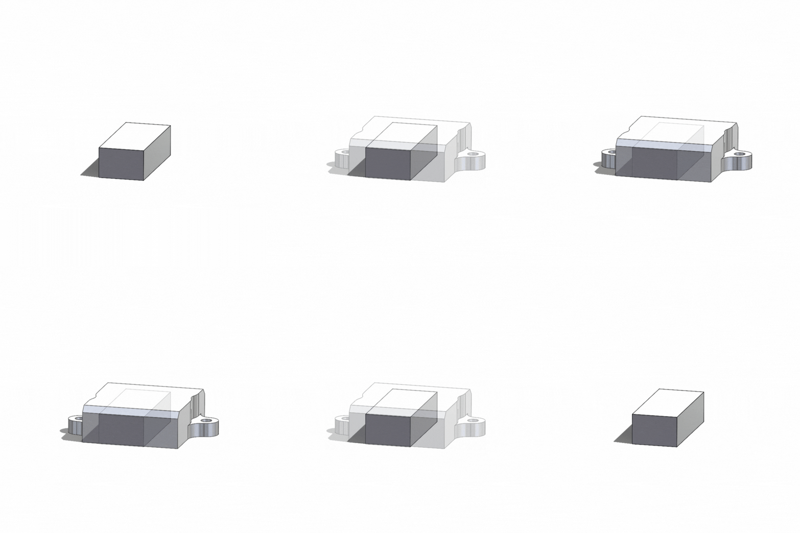
Figure 6 – Aluminium block design change
Conclusion
The data is clear: Scenario 1 is the superior approach. By utilizing a dual-gasket “sandwich” and standard aluminum extrusions, we achieved a thermal reduction of up to 2°C over complex mechanical mounts while significantly simplifying the assembly process and reducing manufacturing costs.

Amar Glavić
The Designer
Amar is our Senior Product Design Engineer and resident "machine whisperer." With almost a decade of experience in the R&D trenches, he lives at the intersection of industrial design and hardcore engineering. Whether he’s navigating complex electro-mechanical integration or refining a prototype for mass production, Amar has a knack for taking a vague concept and turning it into a functional, market-ready reality that’s even better than you imagined.

S