Neoden4 PnP experience
Due to the increase in the demand for the production of larger quantities of electronic hardware we had to consider expanding our capacities to the realm of manufacturing. However, this demand was yet to become high enough to justify equipment for mass production. For that reason, we decided to go with the equipment that would suit our small batch production needs the best.
Our first pick and place machine
After some research, what we found was the Neoden4 Pick and Place machine. Besides the pick and place machine, there were also their reflow oven and a manual stencil printer. This was just enough for what we needed and the price was very much in the range of our budget at the time.
As soon as we had our workshop space ready, we got to the assembling of the newly acquired equipment. As per our custom, we managed to assemble everything without using the manuals. We found these tucked in with all other accessories later on. Everything was set up and ready to use in a few hours or so.
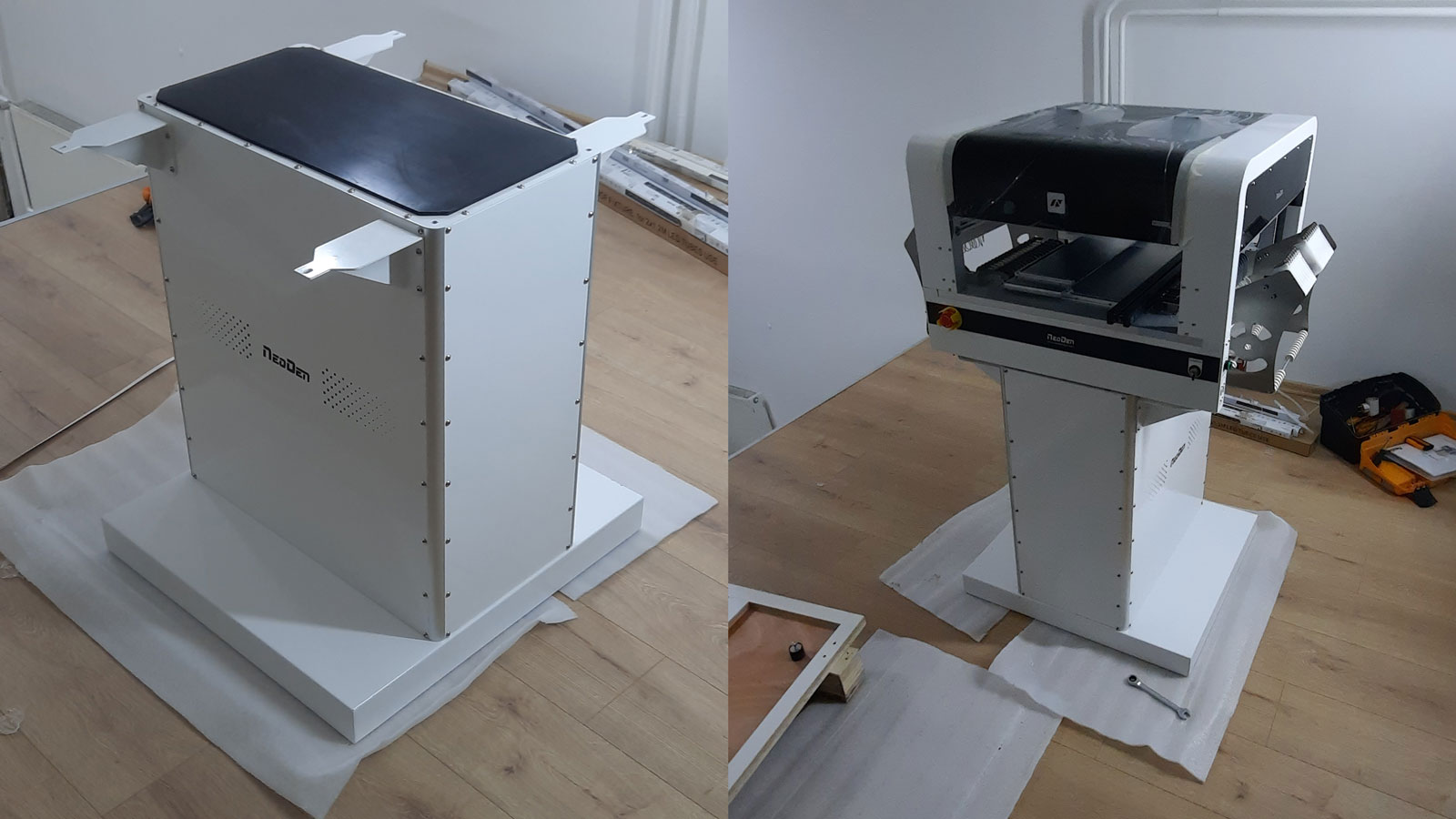
Assembling our first pick and place machine
We were really excited to try the new gear. This will enable us to do so much more! To create better quality products and faster at that!
But very soon we discovered that we may need to curb our enthusiasm a little bit.
The stencil printer was no problem, we quickly got the hang of it, and started using it even before we got the machines ready. The reflow oven wasn’t too difficult to use either. We got a somewhat ok profile in a few iterations of measurements with the temperature probe that we received with the oven. Later we adjusted the profile to be closer to what the one the solder paste manufacturer provided. This was to ensure the best quality of the solder, and it worked great.
The pick and place machine on the other hand was a whole another story.
One sheet to rule them all
It was time to whip up those manuals and go through everything very carefully. Where manuals were not enough, we tried the internet with variable success. This being a very narrow niche meant that all the educational material was all but non-existent.
The designs we had were done in KiCAD and we had to export them to the CSV spreadsheet formatted specifically for this pick and place machine. The fact that we found two different templates on the internet did not help of course. Later we found what each of these is used for.
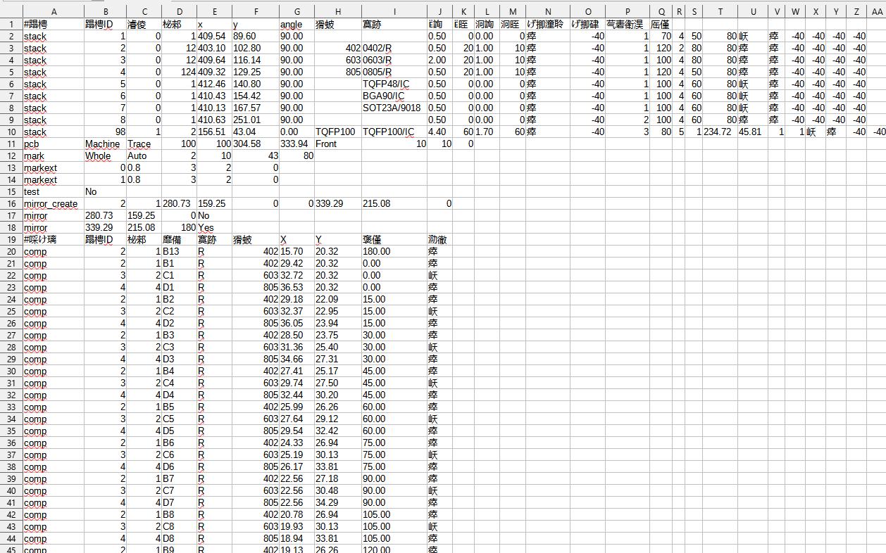
We’re yet to learn Mandarin…

What is the difference between Mid, Ref and Pad?
We found that files generated by the pick and place machine were in English. This helped a lot with understanding the template. To figure out what all of these fields in the template are for, we had to try different settings on the machine and test after modifying each of the values.
This was a major step in getting the machine to work as intended. Now, we were able to automate the conversion process from the KiCAD (or any other EDA software for that matter) to the Neoden4 Pick and Place machine.
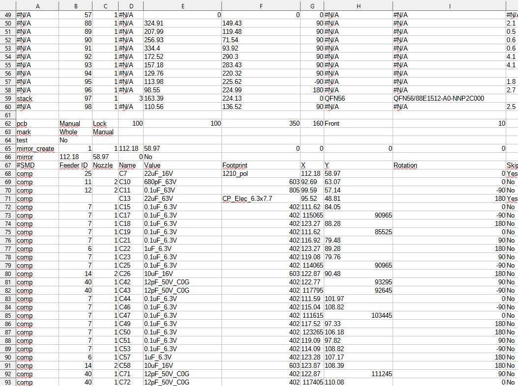
Well, this kinda makes sense now
We also figured out how the positions in KiCAD relate to the positioning of the machine’s tool head. The machine’s coordinates are shown when the tool head is being moved, and these can be used to get the reference position. This reference position can be then used to recalculate all other positions.
Angles also need to be recalculated as KiCAD uses 0° to 360° angles, while Neoden4 Pick and Place machine uses -180° to 180°.
So how does the template work?
The rows following the first row are the settings for the feeders. The first row, of course, is for the names of the columns.

Settings for the feeders
If the first column contains the word stack, the machine will read the settings. The column type is to choose regular (0) or static feeders (1). The rest of the columns correspond to the values in the GUI of the machine. The settings for the static feeder differ a little bit, since the values for the feed rate, torque and peel strength are substituted for the values of the X and Y coordinates of the top right and bottom left component on the static feeder. You can add rows for as many feeders as you need, after which you add the rest of the settings.
After the feeder settings comes the information about PCB Feed Settings and Panelized PCB origin. Everything below this is for the components. If the cell in column #SMD contains the word comp the machine will read the settings for this component. The rest of the columns correspond to what can be seen in the machine’s GUI.
Be sure not to have any invalid values for the Feeder ID or the Nozzle, as these will cause an error and you will have to restart the machine in the middle of the process.
In case something like this does happen to you, don’t worry, there is an easy solution to continue the process from where it stopped. First, of course, you need to detect what caused the problem, by checking the Component list in the PCB information tab and correcting the value. There is an option to open the spreadsheet file on the machine. You can first duplicate the file, and then open it to change the values in the Skip column for all components that preceded the one that caused the failure to Yes. Save these changes and run this file instead to continue the process.
As for the other template, the Mid, Ref and Pad values are all the same, and this template can be used to import (File Import buttons) the values when editing the PCB information. This is not the best approach since, this way, you would have to enter values of Feeder ID and Nozzle for all components. That can get very cumbersome for larger projects.
May the real PCB assembly commence!
We finally tamed the beast, and we were able to get some PCBs assembled. Since the initial PCBs, we have produced over 100 more assembled PCBs. There were still some quirks to figure out, but these were not major causes for worry. We also got some equipment for easier handling of the cut tapes and attaching the peels. This did wonders for the reliability.
Now that we got the hang of everything we can finally say that we have a real small-batch manufacturing process. We look forward to the future challenges in expanding our manufacturing capabilities.
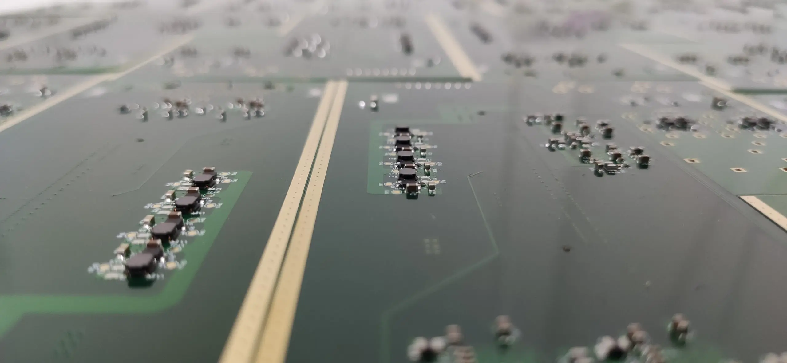
PCBs to the infinity and beyond!
These machines seem reliable enough for what we do, and although there are a few hiccups here and there, we got familiar with the machine enough to know how to deal with them when they do happen.
As for the future, who knows, maybe we’ll have to increase our output so much so that we require some bigger machines soon. We sure hope so ![]()
About the author

Amar Glavić
The Designer
Amar is our industrial designer, mechanical engineer, graphic designer, professional machine whisperer and takes many other roles...shapes and forms when required. He can and will design the thing you need better than you can imagine it.

S
