
USB Dongle programming interface
A versatile USB Dongle Programming Interface, based on a CP2102-GM chip, offers fast data rates, low power consumption, and RX/TX correction switch. Ask for a quote!Build your own!Overview
The USB Dongle Programming Interface is a versatile solution for all your low-power USB to UART communication needs.
With its built-in RX/TX switch, you can easily switch between receive (RX) and transmit (TX) pins, making it a convenient option for debugging and programming.
This is our USB to UART dongle programming interface. It is based on CP2102-GM

This compact and reliable dongle is based on the CP2102-GM chip, which offers fast data rates, low power consumption, and a wide operating temperature range. It is easy to use and compatible with a wide range of devices and operating systems.
With the CP2102-GM USB Dongle Programming Interface, you can quickly and easily connect your devices for programming and debugging. It is perfect for use with microcontrollers, sensors, and other low-power devices.
The CP2102-GM USB Dongle Programming Interface is the perfect tool for any engineer, maker, or hobbyist looking to connect their devices for programming and debugging. It is available for purchase from us, or you can use the available files to make your own custom version.
You can order them from us or use the files and make your own.
Features
- Based on the reliable and high-performance CP2102-GM chip
- Fast data rates up to 3 Mbit/s
- Low power consumption
- RX/TX correction switch
- Wide operating temperature range (-40°C to 85°C)
- Compatible with a wide range of devices and operating systems
- Compact and portable design
- Simple to use
- Customizable
Tech Specs
- Single-Chip USB to UART Data Transfer
- EEPROM
- 3.3V output
- USB Spec. 2.0 compliant (full speed 12Mbps)
- Supported on Windows, Mac and Linux
- Supply voltage:
- Self-powered: 3.0 to 3.6V
- USB bus powered: 4.0 to 5.25V
- Temperature range: -40 to 80°C
_3_switch")
Download
Below is a link to our GitHub repository. Here you can find the PCB connector footprint library, KiCAD project as well as an STL for a 3D printable enclosure.
How to use this USB dongle
1. Connector footprint setup
Import the connector footprint for one of our connector cable options to KiCAD (or other EDA), or use your own
3. Plug the USB dongle
Plug the USB dongle into your PC and the connector of your choice to the PCB you’re programming
2. Connect the cable
Connect the USB dongle with the cable connector of your choice
4. Start the data transfer
Now that everything is connected you can start using the device for it’s intended purpose. Good luck!
Cable Options
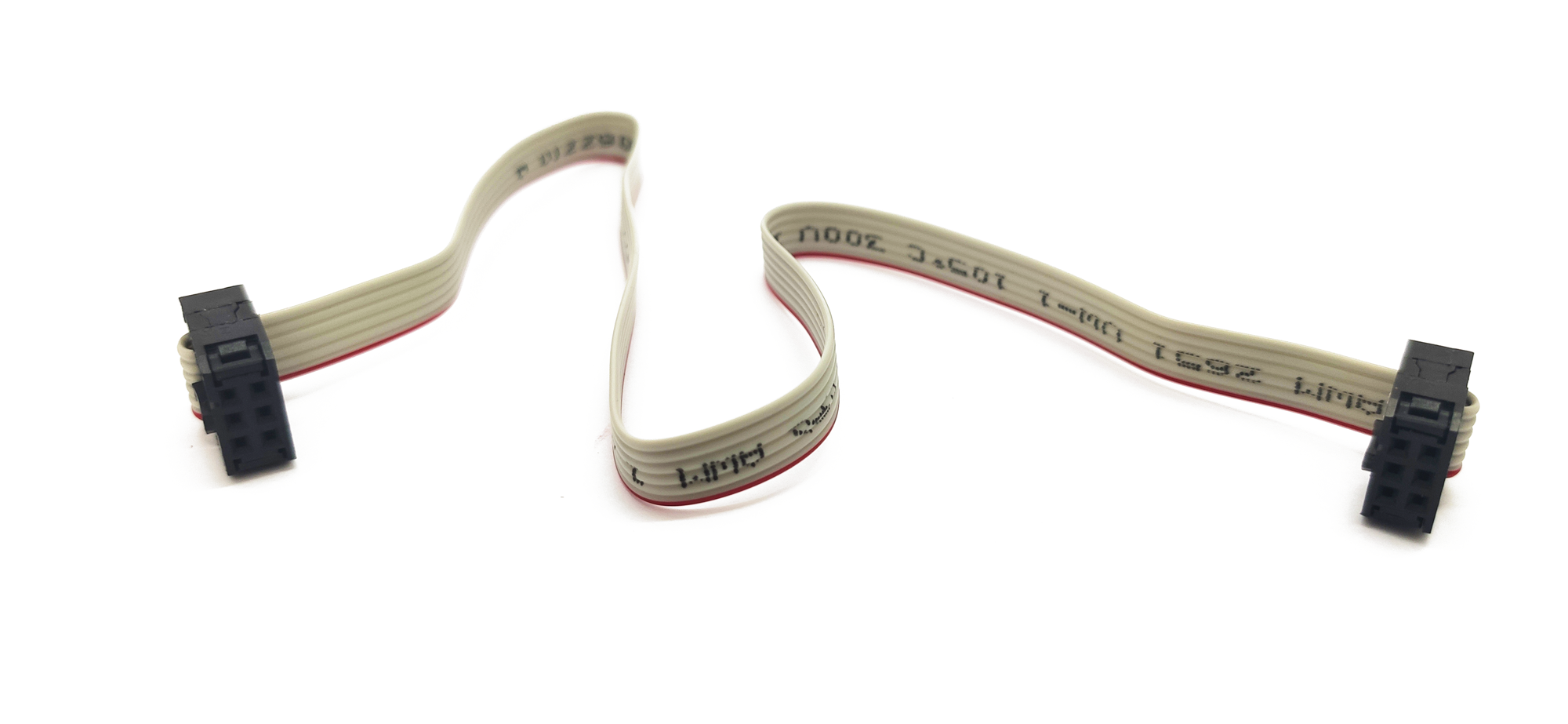
2×3 2.54mm pitch to 2×3 2.54mm pitch
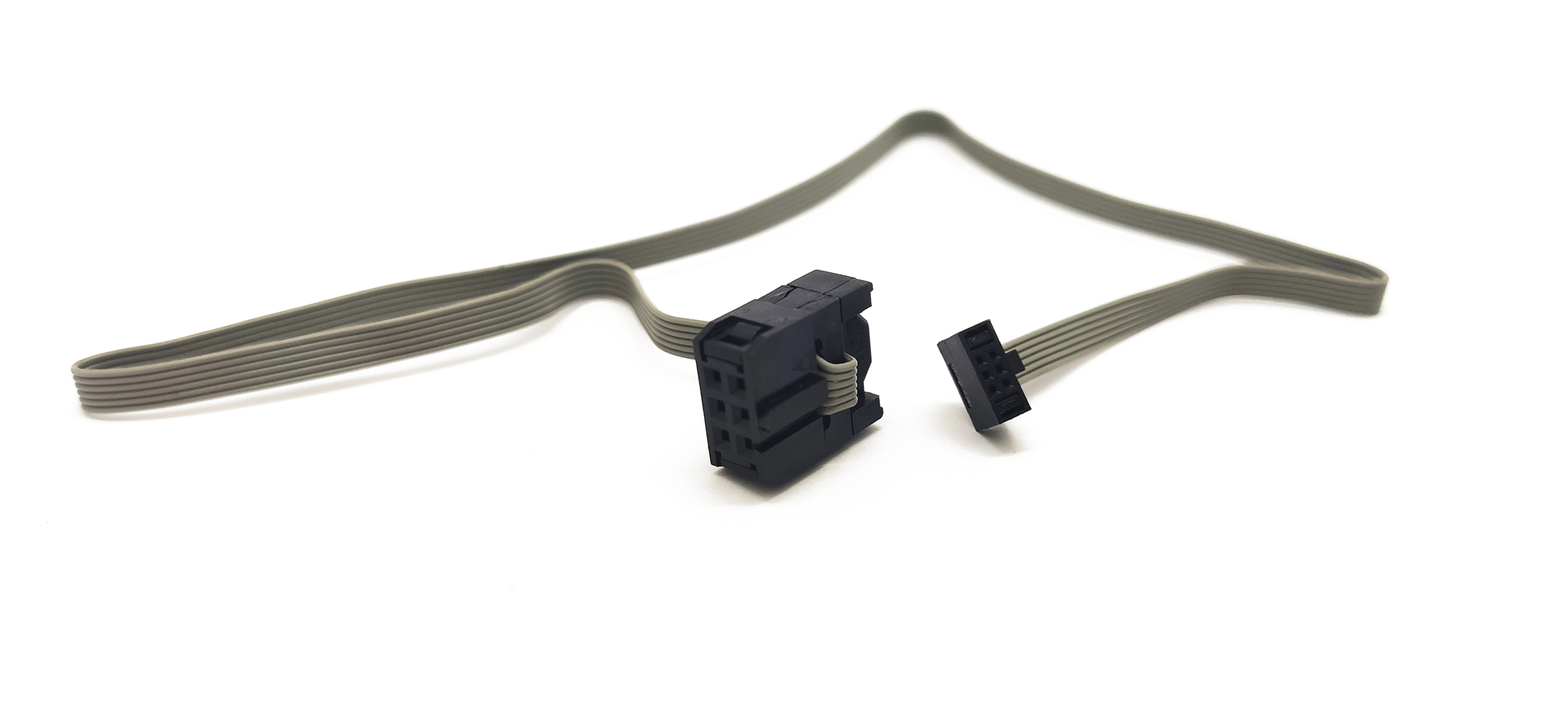
2×3 2.54mm pitch to 2×3 1.27mm pitch
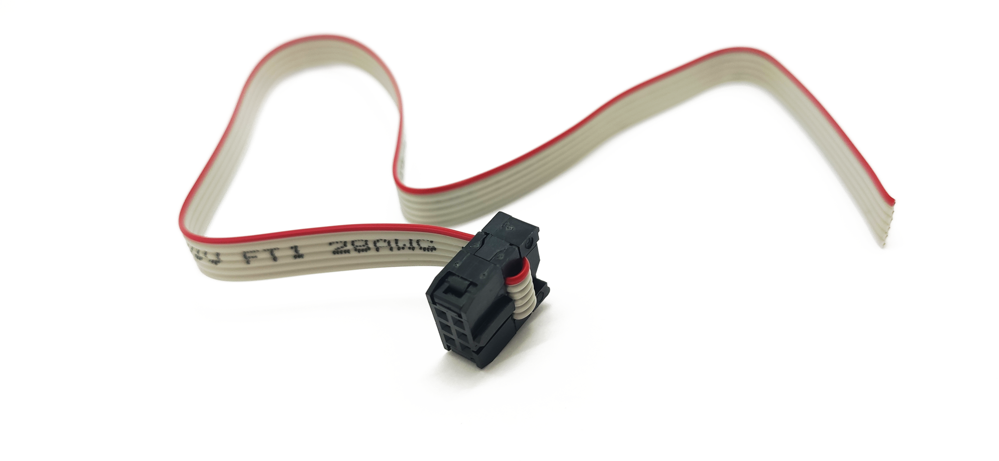
2×3 2.54mm pitch to open
S